# Still Hand-Inserting Transformers and Relays? Here is What Your Throughput Is Costing You
Walk into almost any DIP assembly line in the Pearl River Delta, and you will see the same arrangement: a Wave Soldering machine flanked by manual insertion stations. At the last two or three stations, operators are hand-placing transformers, connectors, relays, and fuse holders — the so-called "odd-form" components that do not fit standard radial or axial tape packaging.
These stations are often the quiet bottleneck of the line. Not because manual insertion is inherently slow — skilled operators can be fast. But because the consistency of that speed changes with every shift change, every new hire, and every product mix variation. And the defect patterns — floating high, missing insertion, reversed polarity — are almost invisible to downstream inspection until the board fails functional test.
## The Hidden Penalty of Manual Odd-Form Insertion
Odd-form components are defined by what they are not: they are not radial, not axial, not SMD. They come in trays, tubes, or loose bags. Their lead pitches vary. Their bodies are asymmetrical. And because they are non-standard, most factories assume they simply cannot be automated.
That assumption carries real costs.
The first is **throughput variability**. A hand-inserted connector takes between 4 and 10 seconds depending on operator familiarity, part orientation, and how the part is presented. Over a production run of 5,000 boards with 4 odd-form components each, that variability can add 8 to 16 hours of unplanned labor — per shift.
The second is **defect rate**. Manual odd-form insertion consistently produces higher rates of floating high (components not fully seated), misinsertion (wrong orientation), and reverse insertion (polarity errors). For a transformer with 6 to 10 pins, even a single non-seated pin can cause a field failure that costs 20 to 50 times the board's assembly value to repair.
The third is **rework cost**. In a typical DIP line, odd-form defects are only caught during AOI or functional test. By that point, the board has already passed Wave Soldering and cleaning. Rework requires desoldering the component, cleaning the through-holes, reinserting, and re-soldering — a sequence that takes 3 to 5 minutes per board and often damages adjacent components.
When these three factors are added together, the per-board cost of manual odd-form insertion is significantly higher than the per-operator wage. The wage is visible. The rework, throughput loss, and quality variance are not.
## How Vision-Guided Automation Changes the Calculation
Odd-form insertion automation exists precisely for this gap. The technology has matured beyond specialized custom machines to modular, programmable platforms that can handle a wide range of non-standard components within a single setup.
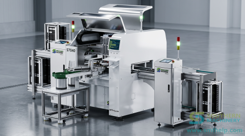
A machine such as Southern Machinery's **S-70LD Odd Form Insertion Machine** uses industrial computer control with vision guidance to locate, orient, and place components onto the PCB. The vision system identifies the part's lead geometry regardless of tray presentation, compensating for component tolerances and packing variation.
The key advantages over manual insertion:
**Consistent insertion force.** Each component is seated to the same depth, eliminating floating high. For a transformer with 8 pins, every pin penetrates the PTH to the programmed depth — every cycle.
**Programmable orientations.** Reverse insertion is eliminated because the vision system checks polarity before placement. If the tray presents a part rotated 180 degrees, the machine detects it and either corrects or rejects it.
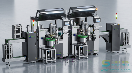
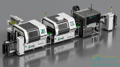
**Integration into the existing DIP line.** The S-70LD is designed as an inline station that connects to the conveyor system upstream of Wave Soldering. It accepts boards via SMEMA handshake and returns them to the same line, with no additional board handling. This means the existing Wave Soldering machine, cleaning equipment, and conveyor infrastructure remain unchanged.
**Predictable cycle time.** Unlike manual stations where speed depends on operator experience, the S-70LD delivers consistent insertion timing regardless of shift or day of week. This makes line balancing predictable and throughput forecasting accurate.
## When Odd-Form Automation Fits, and When It Does Not
Odd-form automation is not universal. It fits best in specific production profiles:
- **Medium to high volume per SKU** — 500+ boards per run, with repeat orders
- **Standard odd-form component types** — connectors, transformers, relays, fuse holders, terminal blocks. These parts have enough dimensional consistency to be handled by programmable tooling
- **Multiple PCB variants sharing component families** — if the same connector is used across 3 different board types, the changeover cost per SKU drops significantly
It fits less well in:
- **Ultra-low volume runs** — below 100 boards per run, where setup time exceeds manual run time
- **Extremely non-standard custom parts** — hand-wound coils, non-standard lead forming, or parts with lead protrusion beyond 2.5mm
- **Factory floor space under 2 square meters** — an inline insertion machine needs conveyor-length space
For most EMS factories supplying the appliance, power supply, and LED lighting industries — the typical Southern Machinery customer profile — the volume and component mix fall comfortably into the "fits well" category.
## The 5-Minute Odd-Form Audit
Here is a quick exercise for your next production review:
1. Count the number of odd-form components on one representative PCB (connectors, transformers, relays, terminal blocks)
2. Multiply by the daily production quantity
3. Multiply by the average measured manual insertion time per part (not the standard time — go measure it on the floor for 10 cycles)
4. Multiply by the observed defect rate for odd-form insertion from your AOI or functional test data
5. Compare the total hours and estimated rework cost to what a programmed machine could deliver at a consistent 3 to 5 second insertion cycle with near-zero insertion defects
Use the calculator below to run the numbers for your line:
[Companion resource: Odd-Form Throughput Calculator — see inline tool below]
If the difference is larger than expected, that gap is your addressable saving — and it has been there since the first odd-form component was hand-inserted on that line.