
PCB-Torförderer zum Aus- und Einfahren
Handbuch
Lesen Sie dieses Handbuch vor der Verwendung * unbedingt sorgfältig durch, um eine ordnungsgemäße Verwendung des Produkts sicherzustellen.
Vorwort
Dank der Produkte des Unternehmens zu kaufen, das Unternehmen zum Ausdruck bringen meinen aufrichtigen Dank. In diesem Handbuch wurden die Hardwarekonfiguration, der Gerätebetrieb und die Wartung elektrischer Schaltpläne beschrieben. Bitte verstehen Sie dieses Handbuch vollständig und achten Sie auf die ordnungsgemäße Verwendung.
Obwohl der Inhalt dieses Handbuchs auf Korrekturen abzielt, wenden Sie sich bei Fragen oder Fehlern bitte an das Unternehmen.
Warnung:
Die Wartung des Geräts darf nur durch Fach- und Servicepersonal oder durch Schulung von Fachpersonal erfolgen
Stellen Sie vor dem Einschalten sicher, dass die externe Eingangsstromversorgung mit der Nennspannung und der Leistung des Geräts übereinstimmt
Bitte sorgen Sie für eine zuverlässige Erdung
Bei der gesamten Mechanik dieses Geräts sollte beim Betrieb auf die persönliche Sicherheit geachtet werden
Notiz:
Bitte lesen Sie dieses Benutzerhandbuch sorgfältig durch, bevor Sie dieses Gerät in Betrieb nehmen. Beachten Sie den Vorsichtshinweis
Installieren Sie dieses Gerät nicht in der Nähe elektromagnetischer Störquellen
Ändern Sie nicht die elektrische Box von Hardware- und Softwareprogrammen, die Transformation erfolgt
Achtung,
please keep this manual press the manual requires maintenance of equipment
Although the contents of this manual are correct, please contact us if you find any doubts or errors.
packing list:
口 Core machine
口 User Manual
口 as customers have special requirements, please refer to procurement contracts check
Contents
CHAPTER 1 INTRODUCTION
1.1 Overview
1.2 Technical Data
Preparation before use
CHAPTER 2 MACHINE OPERATION
2 .1 boot precautions
2 .2 Operating Instructions
CHAPTER 3 DESCRIPTION OF THE PROBLEM 7
CHAPTER 4 MAINTENANCE 8
Chapter 1 Introduction
1.1 Overview
Used for SMT production line connection transmission, and can make a temporary aisle
This machine features:
Adopt Panasonic PLC, ressaix stepping, precision ball screw
1.2 Technical Parameters
Project | The main parameters |
PCBtransportation direction | Left to right |
power supply | AC220 50 / 60Hz power 5 0 W. |
control method | Button plus Panasonic PLC control. |
Type of transmission surface | Strip |
PCB thickness | 0.7 to 30 mm . |
Conveying height | 880~920 ( adjustable ). |
Preparation before use
Please use 220V single-phase 50Hz capacity fixed power supply above 200W
The machine must be safely grounded and must be connected to the ground bus
The ground wire must be well fixed to the metal part of the fuselage
To ensure safety, it is forbidden to bring your body close to the running equipment
Do not install the machine in dust, oil mist, conductive dust, corrosive gases, flammable gases, moisture, shock, vibration, high temperature and outdoor environment.
Avoid using corrosive solvents to wipe the machine, neutral detergent should be used
Please keep this price manual for future maintenance and maintenance.
Notes:
There is no reliable grounding and there is a danger of electric shock.
After the air is connected, the cylinder valve will act. Please do not put your hand into the machine to prevent pinching.
Chapter 2 Machine operation
2..1 Boot precautions
To ensure safety, physical contact with moving parts is prohibited.
Check for any debris in the machine.
Check for any debris or PCB on the track.
2.2 Instructions
Button function description
Automatically – the knob is turned to the “auto” position word, into the automatic operation device
Manual – When the knob is rotated to the position of “Manual”, the device enters the manual operation state
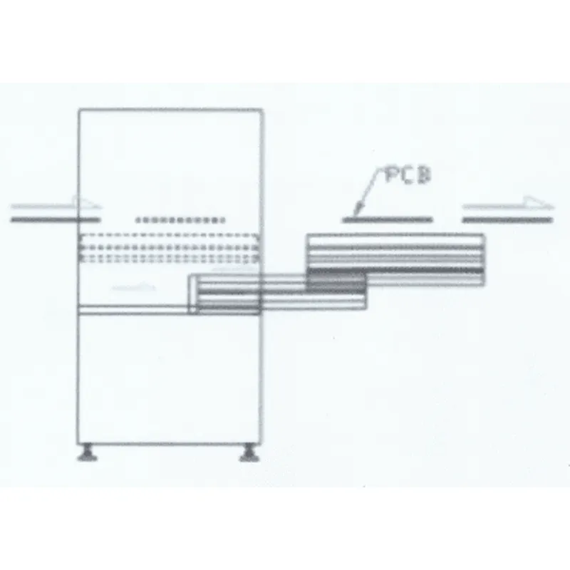
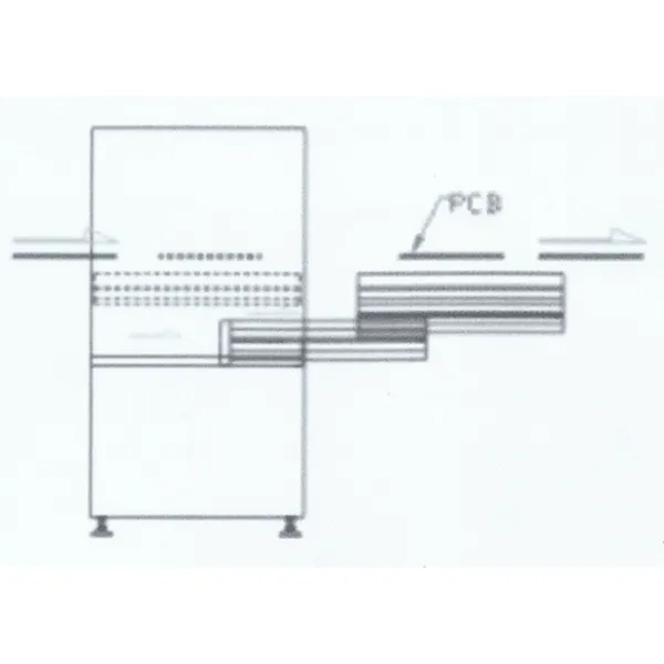
Extend – when running manually, click on the “Extend” button and the docking platform extends out of the rack.
Retracting – When running manually, click the “ Retract ” button, the docking platform will retract the position in the rack , automatically run the device alarm, click the button, the device alarm clears
Pause – When the “Pause” button is pressed, the docking station platform will no longer extend outside the rack
Emergency stop – when the “Emergency stop” button is pressed, the device stops all running actions
Figure 1
Chapter 3 Fault Description
3.3.1 Fault handling and maintenance equipment must do the following points:
The principles familiar with the equipment and electrical schematics.
Familiar with the installation position of each mechanical device and electrical equipment in the equipment, and understand its performance and role.
Correctly analyze the cause of the fault.
Find the faulty part and the failed component
Targeted maintenance.
3.3.2 Frequently fault causes and troubleshooting
Fault content | cause of issue | Approach |
Jam into the board | The height of the left side is different from the height of the upper computer. | Use a spanner wrench to adjust the threaded rod to make the height consistent |
Belt does not turn | Motor is damaged or the belt is too loose | Replace the motor or adjust the tension to tighten the belt |
The main power switch indicator is off. | The switch is broken, the wire is loose, the power cord Open circuit | Unplug the plug and open it to make the panel. Check if the thread is loose. Wenn es locker ist und neu gecrimpt wird, wenn es nicht locker ist, ersetzen Sie bitte den Knopf |
Kapitel 4 Wartung
Wöchentlich
Überprüfen Sie, ob das Transportband zu locker ist, und halten Sie das Band sauber.
Wischen Sie das verschmutzte Öl mit einem Tuch oder Papier ab und schmieren Sie dann die Kugelumlaufspindel.
Testen Sie, ob die Lieferung des Produkts reibungslos verläuft.
Überprüfen Sie die Riemenlaufbahn auf Verschleiß.
Leitspindel mindestens 2 Wochen ölen.
Benutzerhandbuch zum Aus- und Einfahren des Gate-Förderbands für Leiterplatten von Shenzhen Southern Machinery Sales And Service Co., Ltd