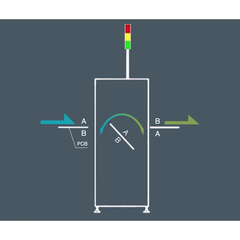
PCB-Wendeförderer
Handbuch
Lesen Sie dieses Handbuch vor der Verwendung * unbedingt sorgfältig durch, um eine ordnungsgemäße Verwendung des Produkts sicherzustellen.
Vorwort
Dank der Produkte des Unternehmens zu kaufen, das Unternehmen zum Ausdruck bringen meinen aufrichtigen Dank. In diesem Handbuch wurden die Hardwarekonfiguration, der Gerätebetrieb und die Wartung elektrischer Schaltpläne beschrieben. Bitte verstehen Sie dieses Handbuch vollständig und achten Sie auf die ordnungsgemäße Verwendung.
Obwohl der Inhalt dieses Handbuchs auf Korrekturen abzielt, wenden Sie sich bei Fragen oder Fehlern bitte an das Unternehmen.
Warnung:
Die Wartung des Geräts darf nur durch Fach- und Servicepersonal oder durch Schulung von Fachpersonal erfolgen
Stellen Sie vor dem Einschalten sicher, dass die externe Eingangsstromversorgung mit der Nennspannung und der Leistung des Geräts übereinstimmt
Bitte sorgen Sie für eine zuverlässige Erdung
Bei der gesamten Mechanik dieses Geräts sollte beim Betrieb auf die persönliche Sicherheit geachtet werden
Notiz:
Bitte lesen Sie dieses Benutzerhandbuch sorgfältig durch, bevor Sie dieses Gerät in Betrieb nehmen. Beachten Sie den Vorsichtshinweis
Installieren Sie dieses Gerät nicht in der Nähe elektromagnetischer Störquellen
Ändern Sie nicht die elektrische Box von Hardware- und Softwareprogrammen, die Transformation erfolgt
Achtung,
Bitte bewahren Sie dieses Handbuch auf. Das Handbuch erfordert die Wartung der Ausrüstung
Obwohl der Inhalt dieses Handbuchs korrekt ist, kontaktieren Sie uns bitte, wenn Sie Zweifel oder Fehler feststellen.
Packliste:
口 Kernmaschine
口 Benutzerhandbuch
口 Da Kunden besondere Anforderungen haben, beachten Sie bitte die Prüfung der Beschaffungsverträge
Inhalt
KAPITEL 1 EINLEITUNG
1.1 Overview
1.2 Technical Data
Preparation before use
CHAPTER 2 MACHINE OPERATION
2 .1 boot precautions
2 .2 Operating Instructions
CHAPTER 3 DESCRIPTION OF THE PROBLEM 7
CHAPTER 4 MAINTENANCE 8
Chapter 1 Introduction
1.1 Overview
Used for turning over PCB or fixture in SMT industry
This machine features:
Adopt Panasonic PLC, stepping Lemire
Can achieve flip the PCB board
1.2 Technical Parameters
Project | The main parameters |
PCBtransportation direction | Left → right |
power supply | AC220 50 / 60Hz power 15 0 W. |
control method | Touch screen plus Panasonic PLC control . |
Type of transmission surface | Strip |
PCB thickness | 0.7 to 30 mm . |
Conveying height | 850 to 950 mm ( foot cup adjustable ). |
Body number | |
Touch screen password | no |
Preparation before use
Please use 220V single-phase 50Hz capacity fixed power supply above 200W
The machine must be safely grounded and must be connected to the ground bus
The ground wire must be well fixed to the metal part of the fuselage
To ensure safety, it is forbidden to bring your body close to the running equipment
Do not install the machine in dust, oil mist, conductive dust, corrosive gases, flammable gases, moisture, shock, vibration, high temperature and outdoor environment.
Avoid using corrosive solvents to wipe the machine, neutral detergent should be used
Please keep this price manual for future maintenance and maintenance.
Notes:
There is no reliable grounding and there is a danger of electric shock.
Chapter 2 Machine operation
2.1 Boot precautions
To ensure safety, physical contact with moving parts is prohibited.
Check for any debris in the machine.
Check for any debris or PCB on the track.
2.2 Instructions
2. 2. 1 Operation page
Figure 1
Button description
Automatic start –After the device resets to zero, the pass-through mode button is red, click the button, and the device enters the flap automatic running state.
Reset – Click the button in the stop state, the device returns to zero; when the device automatically runs the fault alarm beep, the abnormality is processed, and the button device is used to cancel the alarm state and continue to run.
Stop – click the button, the device stops all running
Direct mode – before the automatic start, click the button, when the button turns purple, click auto start, the device enters the through mode
Manual page – click to enter the manual run screen
Parameter page – click to enter the parameter settings page
I/O Monitoring – Click to enter the I/O Monitoring page
Location Settings – Click to enter the location settings page
Signal description
“ XD into the board signal ” – Board signal from the host computer
“ YE requires board signal ” – the board signal from the local machine
“ X5 output signal ” – the output signal sent by the lower computer to the machine
“ YF has board signal ” – the unit has a board signal from the machine
Text description
Production count – the number of production effluent plates
2. 2.3 Location settings page
Position adjustment step description
Click reset back to zero translational axes to be finished, click “position adjustment” button, to enter the position adjustment Click “Manual” button, the device enters the manual operation state, click on the “jog mode” button inthe position adjustment page, turns into the green Jog mode
2. Click on “ + “” – “The button is rotated to the corresponding position , long press the corresponding save button, hear the beep, position adjustment is completed
Button description
Save into the board position – in the jog mode, long press the button, the board entry is saved, the value of the previous input box changes
Save turn Slot – jog mode, press the button, turn the plate-save completion foregoing numerical value input box changed
To the board position – manual operation, non-jog mode, click the button, rotate to the board position
To the flip position – when running manually, non-jog mode, click the button, rotate to the flip position
2.24 Parameter setting description
Input box description
Exit delay setting – when the track is automatically run out, the PCB leaves the stop sensor and reaches the set time to stop the output.
Transmission timeout alarm setting – during automatic operation, the board transfer time is up to the set time, and the device alarms buzzer
Rotating part conveying speed setting – setting of conveying speed of rotating mechanism, the larger the setting value, the larger the conveying speed, it is recommended to be less than 15000
Rear extension speed setting – the setting of the conveying speed of the cleaning docking station. The larger the setting value, the larger the transmission speed. It is recommended to be less than 15000.
Brush speed setting – cleaning the rotation speed setting of the brush of the docking station mechanism, the larger the setting value, the larger the transmission speed, it is recommended to be less than1500 0
1.2.4 Input and output screen description
It can monitor the working status of each electrical component of the device, red is not working, green is working
2.25 manual operation page description
Button description
Manual – After resetting to zero, click the button to enter the manual running state.
To the board position – when running manually, in the non-jog mode, click the button to rotate to the board position
To the flip position – when running manually, in the non-jog mode, click the button to rotate to the flip position
Rotating part into the board transfer – when running manually, when the rotating part is in the board position, click the button, and the rotating mechanism will transmit in the board conveying direction.
Rotating part out of the board transfer – when running manually, when the rotating part is in the flipping position, click the button, the rotating mechanism will send the board in the conveying direction
Clamping cylinder – when operating manually, click the button to clamp the cylinder
Blocking the cylinder – when running manually, click the button to block the cylinder from rising
Chapter 3 description of the problem
3.3.1 Fault handling and maintenance equipment must do the following points:
The principles familiar with the equipment and electrical schematics.
Familiar with the installation position of each mechanical device and electrical equipment in the equipment, and understand its performance and role.
Correctly analyze the cause of the fault.
Find the faulty part and the failed component
Targeted maintenance.
3.3.2 Frequently fault causes and troubleshooting
Fault content | cause of issue | Approach |
Jam into the board | The height of the left side is different from the height of the upper computer. | Use a spanner wrench to adjust the threaded rod to make the height consistent |
Belt does not turn | Motor is damaged or the belt is too loose | Replace the motor or adjust the tension to tighten the belt |
The main power switch indicator is off. | The switch is broken, the wire is loose, the power cord Open circuit | Unplug the plug and open it to make the panel. Check if the thread is loose. If it is loose and re-crimped, if it is not loose, please replace the button |
Alarm when flipping | Check whether the front and rear sensors are sensed when flipping | Adjust the position of the sensor and remove the PCB at the front and rear plate gold positions |
Notes:
Repair or replacement of electrical components disconnect the power, the charging operation is prohibited.
Chapter 4 maintenance
Weekly
Check the transport of steel strap is too loose, keep the conveyor belt clean.
Wipe off the dirty oil with a cloth or paper and then lubricate the ball screw.
Test whether the delivery of the product is smooth.
Check the belt track for wear.
Leitspindel mindestens 2 Wochen ölen.
Benutzerhandbuch für den PCB-Wendeförderer von Shenzhen Southern Machinery Sales And Service Co., Ltd